

Steam pressure control in a boiler is a stack of setpoints, not a single dial. The modulating band sits at the bottom, the operating cut-out above it, the manual-reset high limit above that, and the safety relief valve at the top, set at or below the boiler’s maximum allowable working pressure (MAWP). Every number underneath the relief valve is derived downward from it. Plants that work upward instead, starting from the pressure they wish the header had, end up short cycling the burner or leaning on a safety device to do a control device’s job.
This article covers the pressure loop only: how pressure is sensed, how that reading becomes a firing command, and where each cut-out belongs relative to the others. Water level control, TDS blowdown and burner management sequencing follow separate logic. Every range below is a starting point to check against the nameplate MAWP, the relief valve set pressure, and whatever the authority having jurisdiction requires.
How Steam Pressure Control Works on a Fired Boiler
The pressure loop does one job: it turns a pressure reading into a fuel command. A sensing element, either a mechanical pressure switch or a transmitter feeding a controller, sees pressure at the boiler and compares it to a setpoint. Above the setpoint the loop reduces firing rate or cuts fuel; below it, the loop calls for more heat.
Because saturated steam pressure and temperature move together, setting boiler pressure also sets process temperature. A dryer, sterilizer or jacketed vessel that needs a specific steam temperature in the boiler is in effect specifying a pressure, which is why the operating setpoint is a process decision before it is a mechanical one.
Sensing location changes what the control sees. A control piped off the boiler shell reads shell pressure; one piped off a header downstream of a long run reads that pressure minus whatever the piping drops at full flow. On a boiler feeding a long distribution main, the difference shows up as a burner that keeps firing after the shell is already at setpoint. Compare the control’s reading against a calibrated gauge at the same tap, and do the comparison under load, not at idle.
The safety relief valve is not part of the control loop, and treating it as a working upper limit is the most expensive mistake in this stack. Relief valves are mechanical last-resort devices, sized for the relieving capacity the boiler requires, and every lift risks seat damage and a valve that weeps afterward. A boiler that lifts its relief valve during ordinary load swings has a controls problem, not a valve problem.
The Four Pressure Devices on an Automatically Fired Boiler
Four devices divide the work, and US practice treats two of them as non-negotiable. Automatically fired industrial steam boilers require an operating pressure control that shuts off fuel at a preset maximum operating pressure. They also require a separate high steam pressure limit control with manual reset, which keeps pressure from exceeding the MAWP. ASME CSD-1 sets out controls and safety device requirements for automatically fired boilers under 12,500,000 Btu/hr of fuel input; larger and multiple-burner installations generally fall under NFPA 85 instead.
| Device | What it senses | What it does | Reset | Position in the stack |
|---|---|---|---|---|
| Operating pressure control | Boiler pressure against the operating cut-out | Shuts off fuel at maximum operating pressure, restarts at the cut-in point | Automatic, through its differential | Below the high limit |
| High limit pressure control | The same pressure, at a higher threshold | Shuts off fuel to keep pressure below MAWP | Manual reset required | Between the operating cut-out and the relief valve |
| Modulating (firing rate) control | Pressure inside a proportional band | Drives the burner between low and high fire | Continuous, no cut-out | Lowest band, below the operating cut-out |
| Low-fire hold | Pressure during a cold start | Holds the burner at low fire until pressure builds | Releases automatically at its threshold | Active only below its own setpoint |
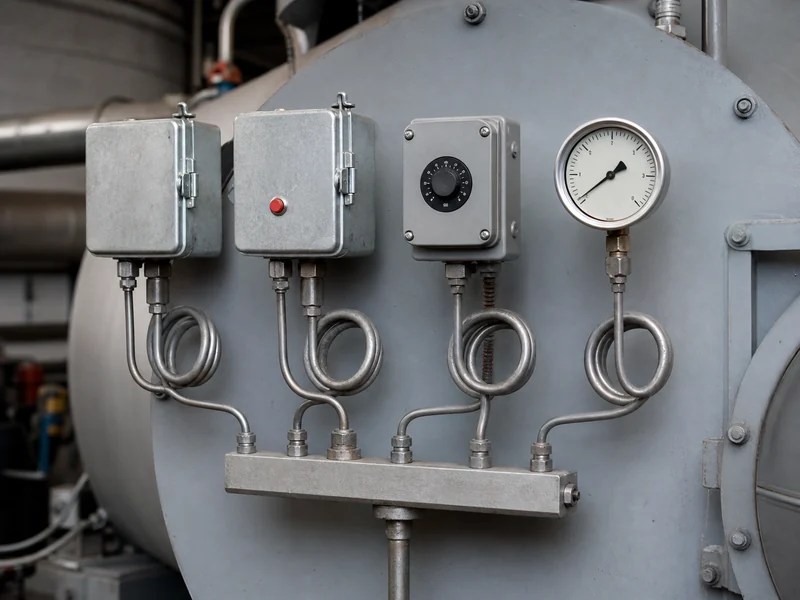
The high limit earns its manual reset by refusing to clear itself. An automatic-reset high limit would let a boiler cycle on a safety limit while nobody noticed that the operating control had drifted or failed, which is exactly the condition the limit exists to expose. Log every high-limit trip and investigate it before pressing reset.
Low-fire hold matters most on boilers that start cold into a demanding load. Firing hard into cold water drives a steep temperature gradient across tubes and tube sheet, and that thermal stress shows up years later as tube-end leaks. Holding low fire until pressure builds costs a few minutes of warm-up and removes the gradient.
Setting the Pressure Stack Below the Relief Valve
Derive the stack from the top down, starting at the relief valve set pressure. Fix the relief valve at or below MAWP. Place the high limit below it with enough margin that a normal overshoot never lifts the valve, and the operating cut-out below the high limit with enough margin that ordinary cycling never reaches the limit. The modulating band sits below the cut-out, so the burner is already at low fire as the cut-out approaches. Published example setpoints vary widely between sources, so treat the ordering as the rule and derive the specific numbers from your own nameplate.
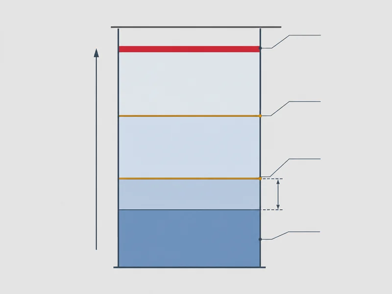
The operating differential decides how often the burner starts. It does not change how much steam the plant gets. Set it too narrow and the boiler short cycles, paying a pre-purge and post-purge loss on every start and wearing the burner and its contactors. Set it too wide and header pressure sags below what the process needs before the burner comes back. Size it against measured behavior: log pressure across a full shift, count burner starts per hour, and check the lowest pressure the process tolerated.
On a modulating burner, the proportional band should bring the burner down to low fire before the operating cut-out opens. When the band is set too high, the burner is still near full fire at the instant the cut-out drops it, and the residual furnace heat pushes pressure past the cut-out toward the high limit. Repeated high-limit trips on a modulating boiler often trace back to this one setting. The control itself is usually fine.
Where a transmitter and PLC handle the loop instead of a mechanical switch, the transmitter range matters as much as the setpoint. A range that places normal operating pressure near mid-span gives the controller usable resolution in both directions; a range chosen far above the working pressure wastes most of the signal and makes the loop feel sluggish. Confirm the reading against a traceable gauge at commissioning.
Choosing the Operating Pressure Your Process Actually Needs
The right operating pressure is the lowest one the process and the distribution system will tolerate, but the boiler itself sets a second floor that has to be checked before the setpoint drops. The US Department of Energy’s steam pressure reduction brief attributes the savings to reduced combustion losses, lower blowdown losses, less radiation loss and less flash steam vented from condensate receivers, all achieved for minimal capital cost. For a plant whose process only needs moderate pressure, that makes pressure reduction a low-capital-cost efficiency measure worth evaluating, provided the process requirement, steam separation and the boiler’s own limits check out first.
Lower pressure is not free at the boiler itself. The same DOE work lists increased carryover, water circulation problems in watertube boilers, higher steam velocities in piping, loss of power in steam turbines, and problems with pressure reducing valves. The carryover mechanism is physical: at lower pressure the same mass of steam occupies more volume, bubbles are larger, and steam leaves the water surface faster, so more water droplets go with it. Boiler manufacturers commonly derate a unit that will run below its design pressure, so put that question to the manufacturer in writing before assuming an answer.
Boiler operating pressure and point-of-use pressure are separate decisions. Many plants deliberately hold boiler pressure up to keep distribution piping small and stable, then reduce pressure at each use point with pressure reducing valves. Where the plant is still selecting equipment, that trade-off belongs to the low-pressure vs high-pressure steam boiler decision, not to the control settings on an installed unit.
Carryover after a pressure cut announces itself if anyone is watching for it. Steam turns wet, drum level starts swinging where it used to sit still, headers begin to hammer, and control valve trim erodes faster than the maintenance interval assumed. Any of those symptoms after a setpoint change is a reason to put the pressure back up and investigate separation and water chemistry before blaming the burner.
Matching Firing Rate Control to Your Load Swing
Firing rate control should follow how fast the load swings, not boiler size alone. On/off control cycles the burner between full fire and off, which works on steady loads but pays a purge loss on every start. High/low control adds an intermediate stage and absorbs moderate swings. Full modulation drives the burner continuously across its turndown range and holds pressure closest to setpoint, which is what a process with rapid, unpredictable demand needs.
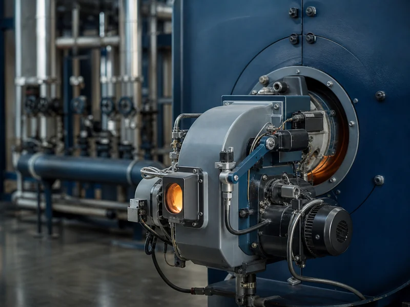
The deciding variable is how fast the load can pull pressure down relative to the boiler’s steam space and water content. A firetube boiler with a large water volume rides through short demand spikes on stored energy, so an on/off burner may hold pressure acceptably. A low-water-content design has almost no buffer: pressure follows demand within seconds, and modulation stops being optional.
Where the pressure loop is one PID loop inside a broader boiler control system, tuning becomes the practical constraint. Gain set too high makes the firing rate hunt, chasing every small pressure wobble. Gain set too low leaves pressure sagging through each load step because the burner responds too late. Tune against a real load change, and watch whether pressure settles within one or two swings.
Diagnosing Unstable Steam Pressure
Work the sensing path before touching a setpoint, because a control that is being lied to cannot be tuned. The order that saves time: confirm the reading against a calibrated gauge, confirm the sensing line and siphon are clear, confirm the setpoints and differential are where the drawings say, and only then adjust the loop.
- Burner short cycles under steady load: the operating differential is too narrow, or the modulating band sits too close to the cut-out. Count starts per hour before changing anything, so the fix can be measured.
- Firing rate hunts and pressure oscillates: controller gain is too aggressive, or the sensing line is restricted enough to add lag. Clear the sensing path before re-tuning gain.
- High limit trips repeatedly: the operating control has drifted, failed, or sits too close to the limit. Treat it as a failed operating control until proven otherwise, and never fix it by raising the high limit.
- Control reading disagrees with the gauge: the siphon is plugged, the sensing line is waterlogged, or the switch has drifted. A blocked siphon can trap pressure and hold a control in a false state indefinitely.
- Burner will not fire while pressure is low: the manual reset on the high limit has not been pushed, or a limit switch has failed open. Check the reset before assuming a burner fault.
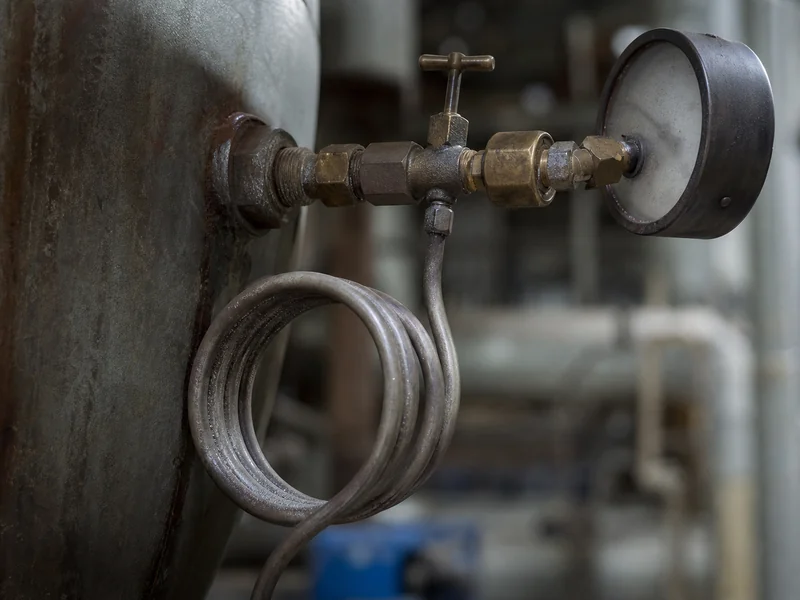
Maintenance on the pressure loop is the part most plants defer. Blow down or clean sensing lines and siphons on a routine cycle, and verify switch or transmitter calibration against a traceable gauge, because drift stays silent until a limit trips. Folding these checks into the periodic inspection of steam boilers is more reliable than treating them as a separate errand nobody owns.
Locking In the Pressure Control Settings
Two settings account for most pressure trouble on an otherwise healthy boiler: the operating differential and the top of the modulating band. Both are usually set once at commissioning, by someone matching the previous boiler’s numbers, and neither is revisited when the process load changes. A short verification pass catches both. Write down the relief valve set pressure, the high limit, the operating cut-out and cut-in, and the modulating band. Confirm each one sits strictly below the one above it. Then confirm the high limit locks the burner out until someone presses its reset.
On a new unit, get the MAWP and the relief valve set pressure before anyone turns a setpoint dial. Those two numbers should be stated in the boiler package documentation, because every other setting in the pressure stack is derived from them, and a stack derived from the nameplate is the one that survives the first cold winter morning when the whole plant calls for steam at once.
Further Reading
- ASME CSD-1, Controls and Safety Devices for Automatically Fired Boilers — ASME / consensus standard. Defines the controls and safety device requirements referenced throughout this article for automatically fired boilers under 12,500,000 Btu/hr fuel input. It does not cover larger multiple-burner units.
- NFPA 85, Boiler and Combustion Systems Hazards Code — NFPA / fire and combustion safety code. Applies to the larger and multiple-burner boiler installations that fall outside the CSD-1 scope; consult it before designing control and interlock schemes for those units.
- Steam Pressure Reduction: Opportunities and Issues — Oak Ridge National Laboratory for the U.S. Department of Energy. Supports the fuel-saving case for lowering boiler operating pressure and lists the countervailing risks, including carryover, watertube circulation problems and higher steam velocities. It addresses system-level pressure decisions, not individual control setpoints.
FAQ
How do you control steam pressure in a boiler?
What is the difference between the operating control and the high limit?
What pressure should an industrial steam boiler run at?
Why does a steam boiler short cycle on pressure?
Can a steam boiler run below its design pressure?
Get Your Custom Boiler Solution
Our engineers analyze your requirements and deliver a tailored boiler system — from capacity sizing to fuel optimization.


